EXAMPLE OF TUBE SHEET LOAD CASE CALCULATIONS

Tube Sheet Load Case
Tube sheet load case calculation involves analyzing the mechanical stresses and deformations experienced by the tube sheet of a heat exchanger or a similar equipment under various operating conditions. The tube sheet is a critical component that supports the ends of the heat exchange tubes and is subjected to significant thermal, mechanical, and hydraulic loads during operation.
The tube sheet load case calculation typically includes:
a) Identify the different loading conditions that the tube sheet may experience during operation. These include internal pressure, external pressure, thermal expansion and contraction, fluid dynamic loads, and any additional loads imposed by connected piping or equipment.
b) Determine the internal and external pressure loads acting on the tube sheet. Internal pressure generates hoop stress in the tube sheet, while external pressure can cause buckling or collapse. Calculate the resulting stresses using appropriate pressure vessel design formulas or finite element analysis (FEA).
c) Analyze the thermal loads on the tube sheet due to temperature gradients between the process fluid and the surrounding environment. Thermal expansion and contraction can induce significant stresses in the tube sheet, especially if it is made of dissimilar materials or operates at high temperature differentials.
d) Evaluate the fluid dynamic forces exerted on the tube sheet by the flowing fluid in the heat exchanger tubes. These forces may include vibration, water hammer, and hydraulic pulsation effects. Determine the resulting stresses and vibrations using fluid dynamics simulations or empirical methods.
e) Consider any additional loads transmitted to the tube sheet from connected piping systems, such as nozzle loads, moments, and axial forces. Account for the effects of pipe expansion, support settlements, and thermal movements on the tube sheet integrity.
f) Assess the fatigue life and creep resistance of the tube sheet material under cyclic loading conditions and elevated temperatures. Consider factors such as material properties, operating cycles, and stress concentrations to predict potential fatigue cracks or deformations over time.
Important parameters in tube sheet load case calculations:
1) Internal Pressure: The pressure differential between the process fluid inside the tubes and the surrounding environment outside the tubes generates hoop stress in the tube sheet. Internal pressure is a critical factor in determining the magnitude of stress and the required thickness of the tube sheet.
2) External Pressure: External pressure acting on the tube sheet, such as atmospheric pressure or pressure from a surrounding fluid, can induce compressive stresses and potentially cause buckling or collapse. Consideration of external pressure is essential, particularly for vacuum service or submerged tube sheets.
3) Thermal Loads: Temperature differentials between the process fluid and the surrounding environment result in thermal expansion and contraction of the tube sheet material. Thermal loads induce thermal stresses in the tube sheet, which must be accounted for in the analysis, especially for materials with low thermal conductivity or high coefficients of thermal expansion.
4) Fluid Dynamic Forces: Fluid flowing through the tubes of the heat exchanger generates dynamic forces on the tube sheet due to fluid velocity, turbulence, vibration, water hammer, and hydraulic pulsations. These fluid dynamic forces can cause localized stresses, fatigue, and vibration-induced failures in the tube sheet.
5) Nozzle Loads: Loads from connected piping systems, such as nozzle loads, moments, and axial forces, are transmitted to the tube sheet. Nozzle loads can result from piping connections, valves, instruments, or other attached equipment. Consideration of these loads is essential to ensure the tube sheet can support the connected piping without excessive deformation or stress concentrations.
6) Material Properties: Mechanical properties of the tube sheet material, such as yield strength, ultimate tensile strength, modulus of elasticity, and thermal expansion coefficient, directly influence its response to applied loads. Selecting appropriate material properties is critical for accurate stress analysis and ensuring the tube sheet meets design requirements.
Importance of Tube Sheet Load Case Calculation:
Tube sheet load case calculation is essential in the design and analysis of heat exchangers and similar equipment for several reasons:
1) Structural Integrity: The tube sheet is a critical component of a heat exchanger, providing support for the heat exchange tubes and maintaining the separation between the fluid streams. Calculating the loads on the tube sheet ensures that it can withstand the mechanical stresses induced by internal pressure, external pressure, thermal expansion, fluid dynamic forces, and nozzle loads without failure or deformation.
2) Safety Assurance: Heat exchangers operate under high pressures and temperatures, making it crucial to ensure their structural integrity and prevent catastrophic failures. By accurately analyzing tube sheet loads, engineers can identify potential failure modes, such as buckling, yielding, or fatigue cracking, and implement design measures to mitigate risks and enhance safety.
3) Optimized Design: Understanding the loads acting on the tube sheet allows engineers to optimize its design for efficiency, reliability, and cost-effectiveness. By considering factors such as material selection, thickness optimization, geometric configuration, and support arrangements, engineers can minimize weight, material usage, and fabrication costs while meeting performance requirements.
4) Code Compliance: Design codes and standards, such as the ASME Boiler and Pressure Vessel Code, specify minimum requirements for tube sheet design to ensure regulatory compliance and operational safety. Tube sheet load case calculations help verify compliance with code requirements, such as allowable stresses, fatigue life, and corrosion allowances, to ensure that the heat exchanger meets industry standards and regulations.
5) Performance Prediction: Accurate analysis of tube sheet loads enables engineers to predict the mechanical behavior of the heat exchanger under various operating conditions, including normal operation, start-up, shutdown, and transient events. This predictive capability allows for proactive maintenance planning, risk assessment, and troubleshooting to prevent unexpected downtime or equipment failures.
Issues and Solution on Tube Sheet Load Case Calculations
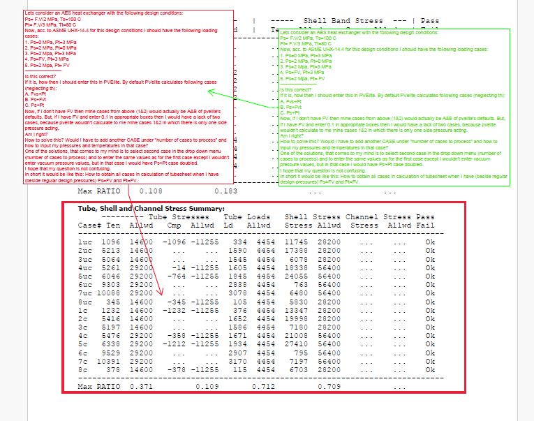
1) Issue: Let’s consider an AES heat exchanger with the following design conditions:
Ps= F.V/2 MPa, Ts=100 C
Pt= F.V/3 MPa, Tt=80 C
Now, acc. to ASME UHX-14.4 for this design conditions I should have the following loading cases:
1. Ps=0 MPa, Pt=3 MPa
2. Ps=2 MPa, Pt=0 MPa
3. Ps=2 Mpa, Pt=3 MPa
4. Ps=FV, Pt=3 MPa
5. Ps=2 Mpa, Pt= FV
———————–
Is this correct?
If it is, how then I should enter this in PVElite. By default PVelite calculates following cases (neglecting th):
A. Fvs+Pt
B. Ps+Fvt
C. Ps+Pt
Now, if I don’t have FV then mine cases from above (1&2) would actually be A&B of pvelite’s defaults. But, if I have FV and enter 0.1 in appropriate boxes then I would have a lack of two cases, because pvelite wouldn’t calculate to me mine cases 1&2 in which there is only one side pressure acting.
Am I right?
How to solve this? Would I have to add another CASE under “number of cases to process” and how to input my pressures and temperatures in that case?
One of the solutions, that comes to my mind is to select second case in the drop down menu (number of cases to process) and to enter the same values as for the first case except I wouldn’t enter vacuum pressure values, but in that case I would have Ps+Pt case doubled.
In short it would be like this: How to obtain all cases in calculation of tubesheet when I have (beside regular design pressures) Ps=FV and Pt=FV.
Solution: Here are the cases per UHX-14.4 and run by PV Elite for your particular case,
1. Ps=0 MPa, Pt=3 MPa , no thermal
2. Ps=2 MPa, Pt=0 MPa , no thermal
3. Ps=2 Mpa, Pt=3 MPa , no thermal
4. Ps=0 MPa, Pt=0 MPa , thermal considered
5. Ps=0 MPa, Pt=3 MPa , thermal considered
6. Ps=2 MPa, Pt=0 MPa , thermal considered
7. Ps=2 Mpa, Pt=3 MPa , thermal considered
There are 2 ways to specifying the vacuum pressures in PV Elite. One is to specify it in the input fields for vacuum pressure. These fields are located on the Load Case tab -> “Vacuum Pressures and Report Options for this Load Case …”
Now, instead of 0 the vacuum pressure is used for the design. The loadcases including vacuum pressure are.
1. Ps=Shell_VAC MPa, Pt=3 MPa , no thermal
2. Ps=2 MPa, Pt=Tube_VAC MPa , no thermal
3. Ps=2 Mpa, Pt=3 MPa , no thermal
4. Ps=Shell_VAC MPa, Pt=Tube_VAC MPa , thermal considered
5. Ps=Shell_VAC MPa, Pt=3 MPa , thermal considered
6. Ps=2 MPa, Pt=Tube_VAC MPa , thermal considered
7. Ps=2 Mpa, Pt=3 MPa , thermal considered
As the differential between the design pressure and vacuum pressure is higher as compared to the differential between the design pressure to 0 pressure, this captures the worst case. Assuming that the design pressure are +ve which they typically are.
Second approach is for setting up the vacuum pressures is to use the higher level design cases and not entering any value in the vacuum pressure fields. You would select from the drop down list the number of design level cases to consider. The first one being design case. Second could be the shell side vacuum case, you will put vacuum pressure as shell side design pressure and tube side design pressure.
This 2nd option is useful if your design pressures are -ve or some conditions change when there is a vacuum such as the design temperature. It gives you more flexibility to modify the design conditions. It also produces more output.
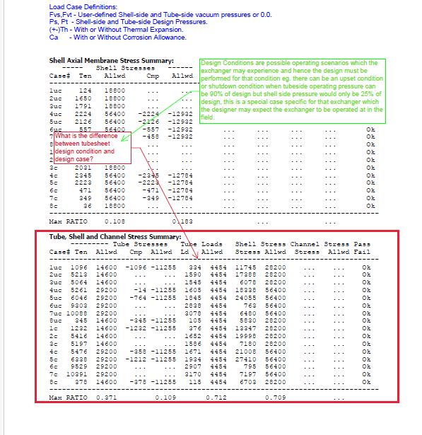
2) Issue: What is the difference between tubesheet design condition and design case?
Solution: Design Conditions are possible operating scenarios which the exchanger may experience and hence the design must be performed for that condition eg. there can be an upset condition or shutdown condition when tubeside operating pressure can be 90% of design but shell side pressure would only be 25% of design, this is a special case specific for that exchanger which the designer may expect the exchanger to be operated at in the field.
3) Issue: Heat exchangers are subjected to a combination of internal pressure, external pressure, thermal expansion, fluid dynamic forces, and nozzle loads, making it challenging to accurately predict the resulting stresses and deformations in the tube sheet.
Solution: Conduct a comprehensive analysis of all anticipated loading conditions using appropriate engineering methods, such as finite element analysis (FEA) or hand calculations. Consider the effects of transient loads, seismic events, wind loads, and thermal gradients to ensure robust design.
4) Issue: The mechanical properties of the tube sheet material, such as yield strength, ultimate tensile strength, modulus of elasticity, and thermal expansion coefficient, significantly influence its response to applied loads. Inaccurate material properties or selection can lead to erroneous calculations.
Solution: Verify material properties against reputable sources, such as material test reports or recognized material databases. Conduct sensitivity analyses to assess the effects of material variability on the tube sheet design. Consider using higher-grade materials or alloys for critical applications.
5) Issue: The geometric configuration of the tube sheet, including the layout and arrangement of tubes, tube pitch, and tube-to-tube sheet joint design, affects its mechanical behavior under loading. Inadequate consideration of geometric factors can result in stress concentrations or inadequate support.
Solution: Optimize the tube sheet geometry to minimize stress concentrations and ensure uniform loading distribution. Consider factors such as ligament efficiency, ligament spacing, and tube pitch to enhance structural integrity. Conduct sensitivity analyses to evaluate the effects of geometric variations on stress levels.
6) Issue: Design codes and standards, such as ASME Boiler and Pressure Vessel Code Section VIII, Division 1, specify minimum requirements for tube sheet design to ensure regulatory compliance and operational safety. Non-compliance with code requirements can result in design rejections or regulatory fines.
Solution: Familiarize yourself with the applicable design codes and standards and ensure that all calculations and analyses adhere to their requirements. Consult with experienced engineers or code experts to interpret code provisions accurately and address any discrepancies or ambiguities.
Conclusion
In conclusion, tube sheet load case calculations are essential for ensuring the structural integrity, safety, and reliability of heat exchangers. However, several challenges and issues may arise during the calculation process, requiring careful consideration and effective solutions.
By addressing issues such as complex loading conditions, material selection, geometric considerations, code compliance, and verification and review, engineers can mitigate risks and ensure accurate and reliable tube sheet designs.
Collaboration among multidisciplinary teams, including mechanical engineers, structural analysts, materials specialists, and code experts, is crucial for conducting comprehensive load case analyses and optimizing tube sheet designs.
Ultimately, by overcoming challenges and implementing appropriate solutions, engineers can achieve optimized tube sheet designs that meet safety standards, regulatory requirements, and industry best practices, ensuring the long-term integrity and performance of heat exchangers in various industrial applications.
Get detailed/ Get files/ Get customized/ Get trained by click link given here https://shreeaasaantech.com/contact-us/
