EXAMPLE OF GENERAL ARRANGEMENT DRAWING OF PRESSURE VESSEL

Image source: https://www.pveng.com/home/asme-code-design/water-softener-vessel-sample/
Sections:
Bill of Material:
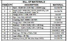
Shell:
It is primary component that contains the pressure. Pressure vessel shells in the form of different plates are welded together to form a structure that has common axis. The main body of the pressure vessel is known as shell. The process of pressure vessel generally occurs in this region. Generally, manhole and hand hole is located in this region. No other nozzle is mainly mounted on it. Internal pressure of the vessel acts more in this region.
Flange:
Flange are used to connect pipes with each other, to valves, to fitting, and to specially items such as strainers and pressure vessel
i.e., welding neck, slip on, Socket welding
Design specification:
Documents detailed design parameters, include vessel dimensions
Material specification and design criteria
Safety considerations:
Include essential safety data such as pressure relief valve settings emergency shutdown procedures and other critical safety measures.
Maintenance Guideline:
Outline recommended Maintenance schedules, inspections and procedures to ensure the longevity and reliability of the vessel
Regulatory Compliance:
Ensure that the vessel data sheet aligns with the relevant industry standards and regulatory requirements.
Design data sheet:
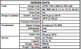
Design data sheet is divided into four parts
1] Code:
The design code refers to a set of rules, standards, or specifications that engineers and designers follow when creating structure or systems. In the context of vessels, such as pressure vessels, common design codes include i.e., (ASME) widely use in north America and internationally it provides rules for the design, fabrication, inspection, testing and certification of pressure vessels
2] Design condition:
The design conditions for vessel typically refer to the specific operating parameters and environmental factors that the vessel is designed to withstand these conditions are crucial for ensuring the safety
3] Examination:
In this process involves compliance with design specifications, safety, standards, and regulatory requirements like impact testing, Radiography and hydro test
4] Service:
the service conditions play crucial role in designing and detailing the pressure vessel the term of service typically refers to the intended use or purpose of the vessel
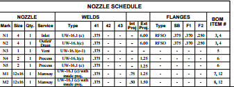
The nozzle schedule is the context of a pressure vessel to the detailed information about each nozzle attached to the vessel or pipe this information is crucial for fabrication. The nozzle schedule typically include
1] Nozzle size: the nominal pipe size of the nozzle, specifying its diameter
2] Nozzle Rating: The pressure rating of nozzle, indicating the maximum pressure it can withstand
3] Nozzle type: Identification of the type of nozzle, such as nozzle for as inlet, outlet, vent, or instrument connection
Same as welds and flanges
Types:
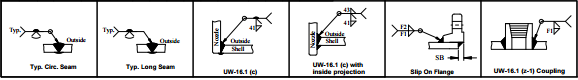
1] Typ. Circ. Seam
It’s a typical circumferential seam in the context of vessel or piping fabrication
2] Type. Long. Seam
It’s called as longitudinal seam the longitudinal seam is a weld that runs along the length of cylindrical component such as pressure vessel
3] UW
UW is stands for typically refers to section of the ASME boiler and pressure vessel code
4] Slip on flange
Slip on flange is a type of flange that is slipped over the end of a pipe and then welded in place
5] coupling
Coupling is refers to a device used to connect two shafts or pipe together for the purpose of transmitting power there are type like pipe coupling, flexible coupling, rigid coupling.
Issue in General Arrangement Drawing
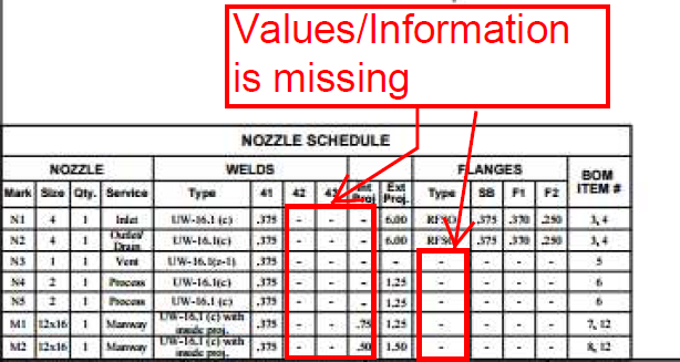
In the Nozzle Schedule the welds size is missing i.e., 41,42 is missing
And the Remaining type of Flanges is missing
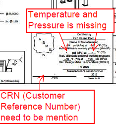
The maximum allowable working pressure and temperature is missing
And the CRN (Customer Reference Number is need to mention in above sample
Issues And Solution on General Arrangement Drawing of Pressure Vessel
Creating a general arrangement drawing (GAD) for a pressure vessel involves various considerations to ensure accuracy, clarity, and compliance with design requirements. Here are common issues that may arise in GADs for pressure vessels, along with potential solutions:
- Dimensional Inaccuracies:
- Issue: Incorrect dimensions or scaling can lead to fabrication errors or clashes during installation.
- Solution: Double-check all dimensions against design specifications and standards. Use CAD software with precise measurement tools to ensure accuracy.
- Lack of Detail:
- Issue: Insufficient detail may cause confusion during fabrication or assembly.
- Solution: Include all necessary components, connections, supports, and instrumentation with clear labeling. Add sectional views or exploded views if needed for clarity.
- Ambiguity in Annotations:
- Issue: Unclear or ambiguous annotations can lead to misunderstandings regarding specifications or assembly procedures.
- Solution: Ensure all annotations are clear, consistent, and conform to industry standards. Use standardized symbols and terminology.
- Inadequate Labeling:
- Issue: Components, connections, and features may not be adequately labeled, leading to confusion.
- Solution: Label all components, including vessels, nozzles, manways, and supports, using a consistent and intuitive naming convention.
- Inconsistencies in Scale:
- Issue: Scale discrepancies between different views or sections can lead to misinterpretation.
- Solution: Maintain consistent scaling throughout the drawing. Use a scale bar or notation to indicate scale in each view.
- Missing Safety Information:
- Issue: Critical safety features or considerations may not be clearly indicated.
- Solution: Highlight safety features such as relief valves, pressure gauges, and access points prominently. Include notes or callouts to emphasize safety considerations.
- Poor Alignment:
- Issue: Components may not be aligned correctly, affecting functionality or aesthetics.
- Solution: Ensure proper alignment of components, nozzles, and supports according to design specifications. Use grid lines or alignment tools in CAD software for precision.
By addressing these issues and implementing the suggested solutions, you can improve the quality, accuracy, and clarity of GADs for pressure vessels, ultimately leading to smoother fabrication, installation, and operation processes.
Get detailed/ Get files/ Get customized/ Get trained by click link given here https://shreeaasaantech.com/contact-us/
