EXAMPLE OF NOZZLE CALCULATIONS
Nozzle
A nozzle is a crucial component in pressure vessels and piping systems, facilitating fluid entry or exit, connecting the vessel or pipe to other equipment or piping, and serving as a location for installation of safety devices or instruments. Nozzles come in various types, including flanged, welded, threaded, socket weld, lined, and special purpose, each designed for specific functions and applications. When selecting and designing nozzles, engineers consider factors such as fluid properties, flow requirements, stress analysis, code compliance, and support and reinforcement needs. Nozzles may impose loads on the vessel or piping system, including pressure loads, thermal loads, moment loads, and external loads, necessitating additional support or reinforcement measures such as reinforcing pads, stiffening rings, or external supports to ensure structural integrity and prevent failure under load. Overall, proper selection, design, and installation of nozzles are essential for the safe and efficient operation of pressure vessels and piping systems in various industrial applications.
Importance of Nozzle Calculation
Nozzle calculations are vital for several reasons:
1) Structural Integrity: Proper calculations ensure that the nozzle can withstand the mechanical stresses imposed by fluid pressure, thermal expansion, and external loads without experiencing deformation, leakage, or failure.
2) Safety: Accurate calculations help prevent catastrophic failures, leaks, or ruptures that could lead to equipment damage, environmental contamination, or injury to personnel.
3) Code Compliance: Nozzle calculations ensure compliance with relevant design codes and standards, such as ASME BPVC, API, or ISO standards, which mandate specific design requirements for pressure vessels and piping systems.
4) Optimized Design: Calculations enable engineers to optimize the design of the nozzle by selecting appropriate materials, dimensions, reinforcement, and attachment methods to minimize weight, cost, and fabrication complexity while meeting performance requirements.
5) Performance: Nozzle calculations consider factors such as fluid properties, flow rates, pressure drops, and erosion/corrosion effects to ensure that the nozzle performs efficiently and reliably over its intended service life.
6) Risk Mitigation: Thorough calculations help identify potential design flaws, stress concentrations, or failure modes early in the design process, allowing engineers to implement appropriate mitigation measures and reduce the risk of operational problems or safety incidents.
7) Documentation and Verification: Properly documented calculations provide a clear record of the design rationale, assumptions, methodologies, and results, facilitating design verification, regulatory compliance, and troubleshooting throughout the equipment lifecycle.
Important Parameters in Nozzle Calculation
1) Fluid Properties: Characteristics such as density, viscosity, temperature, and pressure affect nozzle design and performance.
2) Flow Rate: The desired flow rate through the nozzle determines its size and dimensions.
3) Nozzle Diameter: The diameter of the nozzle opening influences flow velocity, pressure drop, and overall system efficiency.
4) Pressure Rating: The nozzle must be rated to handle the maximum pressure expected in the system without failure.
5) Nozzle Thickness: The thickness of the nozzle wall must be sufficient to withstand internal pressure and external loads.
6) Stress Analysis: Calculations must consider stresses induced by pressure, temperature, vibration, and other factors to ensure structural integrity.
7) Reinforcement: Reinforcing elements such as repads, stiffening rings, or fillet welds may be required to strengthen the nozzle attachment.
8) Material Selection: Nozzle materials must be compatible with the fluid being conveyed and capable of withstanding the operating conditions.
9) Nozzle Loads: Axial, radial, and moment loads on the nozzle from pressure, thermal expansion, equipment weight, and external forces must be evaluated.
10) Code Compliance: Nozzle design must adhere to applicable design codes and standards, such as ASME BPVC, API, or ISO requirements.
11) Nozzle Orientation: The angle and orientation of the nozzle relative to the vessel or piping system affect flow characteristics and stress distribution.
12) Nozzle Flange Rating: Flanged nozzles require flanges with appropriate pressure ratings and dimensions to ensure proper sealing and connection.
13) Nozzle Reinforcement Pad: If required, reinforcement pads should be designed to distribute loads and minimize stress concentrations.
14) Nozzle Welding: Welding procedures, joint configurations, and quality control measures must meet welding code requirements for strength and integrity.
Issue and Solutions on Nozzle Calculation
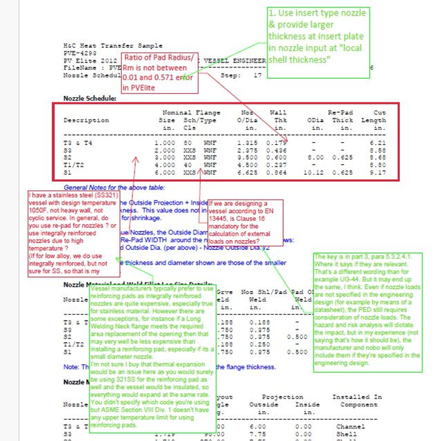
1) Issue: I have a stainless steel (SS321) vessel with design temperature 1050F, not heavy wall, not cyclic service. In general, do you use re-pad for nozzles? or use integrally reinforced nozzles due to high temperature?
(If for low alloy, we do use integrally reinforced, but not sure for SS, so that is my question)
Solution: Vessel manufacturers typically prefer to use reinforcing pads as integrally reinforced nozzles are quite expensive, especially true for stainless material. However, there are some exceptions, for instance if a Long Welding Neck flange meets the required area replacement of the opening then that may very well be less expensive than installing a reinforcing pad, especially if it’s a small diameter nozzle.
I’m not sure I buy that thermal expansion would be an issue here as you would surely be using 321SS for the reinforcing pad as well and the vessel would be insulated, so everything would expand at the same rate. You didn’t specify which code you’re using but ASME Section VIII Div. 1 doesn’t have any upper temperature limit for using reinforcing pads.
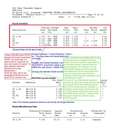
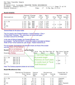
2) Issue: Ratio of Pad Radius/Rm is not between 0.01 and 0.571 error in PVElite
Solution: 1. Use insert type nozzle & provide larger thickness at insert plate in nozzle input at “local shell thickness”
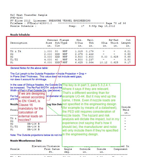
3) Issue: If we are designing a vessel according to EN 13445, is Clause 16 mandatory for the calculation of external loads on nozzles?
Solution: The key is in part 3, para 5.3.2.4.1. Where it says if they are relevant.
That’s a different wording than for example UG-44. But it may end up the same, I think. Even if nozzle loads are not specified in the engineering design (for example by means of a datasheet), the PED still requires consideration of nozzle loads. The hazard and risk analysis will dictate the impact, but in my experience (not saying that’s how it should be), the manufacturer and nobo will only include them if they’re specified in the engineering design.
4) Issue: I am reviewing a fatigue analysis of a vessel with an agitator on the top nozzle which is subjected to external loads fatigue (same situation of the quoted thread).
No pressure or temperature fatigue is expected.
Vessel is analyzing with a FEA considering the external cyclic loads like static, P=0, T=0. Temperature corrected stress amplitude is considered, max stress on welds are multiplied by the correct penalty factor as per table 5.13 and endurance limit is guaranteed.
My “issue” is that with this analysis you are just considering the cyclic stress range, but you are completely ignoring the mean stress (no pressure and temperature) which is much higher that what evaluated by the FEA.
Protection against ratcheting is also verified considering stress given only by cyclic external loads, again ignoring the higher max stress given by the static pressure and temperature + external loads.
Is the fatigue analysis as per annex 3f the correct approach for the described problem?
If yes, at least local failure shall be evaluated considering overall loads?
Can someone provide me some literature reference specifically related to fatigue analysis in ASME/EN code?
Solution: As discussed in ASME PTB-1, there is a mean-stress correction factor built-in to the fatigue curves.
Certainly, check Protection Against Plastic Collapse. And demonstrate Protection Against Local Failure. Likewise, with buckling.
As I mentioned in the referenced thread, make sure that the welds are handled appropriately.
5) Issue: I am laying out a piece of 304 stainless steel equipment with a set through nozzle on an end cap.
My client wants 100% radiography but I am unsure if/how radiography would be done on a set through nozzle in an end cap – it’s a 4″NB nozzle in a 10″NB end cap, all standard weight thickness.
RT on butt welds is straightforward, but I am wondering if I should argue for penetrant dye examination on this weld instead?
Solution: Ultrasonic testing is an option
See ASME V
MANDATORY APPENDIX II INSERVICE EXAMINATION OF NOZZLE INSIDE CORNER RADIUS AND INNER CORNER REGIONS
6) Issue: Failure to perform comprehensive stress analysis may result in underestimation of stresses, leading to structural failure or leakage.
Solution: Conduct thorough stress analysis considering all relevant factors such as pressure, temperature, thermal expansion, and external loads. Use appropriate analytical methods or finite element analysis (FEA) to accurately predict stress distribution and ensure structural integrity.
7) Issue: Incorrect material selection for the nozzle may lead to inadequate strength, corrosion susceptibility, or compatibility issues with the fluid.
Solution: Select materials based on compatibility with the process fluid, operating conditions, and code requirements. Consider factors such as corrosion resistance, mechanical properties, and cost-effectiveness to ensure optimal material selection.
8) Issue: Failure to comply with applicable design codes and standards may result in unsafe designs or regulatory violations.
Solution: Ensure that nozzle calculations adhere to relevant design codes and standards, such as ASME BPVC, API, or ISO requirements. Stay updated with the latest revisions and amendments to ensure compliance with current industry practices.
9) Issue: Relying on incorrect assumptions or simplifications in nozzle calculations may lead to inaccurate results.
Solution: Verify all assumptions and input parameters used in the calculation process. Use conservative estimates and sensitivity analysis to account for uncertainties and ensure robustness of the design.
Conclusion
In conclusion, addressing issues with nozzle calculations is crucial for ensuring the structural integrity, safety, and reliability of pressure vessels and piping systems in industrial applications. By identifying common issues such as inadequate stress analysis, material selection errors, code non-compliance, incorrect assumptions, insufficient reinforcement, improper sizing, and lack of documentation, engineers can implement effective solutions to mitigate risks and ensure accurate design outcomes.
Solutions include conducting comprehensive stress analysis, selecting appropriate materials, complying with relevant design codes and standards, verifying assumptions, incorporating reinforcement elements, optimizing sizing, and maintaining thorough documentation. By following these steps, engineers can design nozzles that meet performance criteria, regulatory requirements, and safety expectations, contributing to the overall reliability and efficiency of industrial equipment and processes.
Regular review, verification, and documentation of nozzle calculations are essential for maintaining design integrity, facilitating design validation, regulatory compliance, and troubleshooting throughout the equipment lifecycle. Ultimately, a systematic approach to addressing nozzle calculation issues ensures the safe and reliable operation of pressure vessels and piping systems in various industrial environments.
Get detailed/ Get files/ Get customized/ Get trained by click link given here https://shreeaasaantech.com/contact-us/
