EXAMPLE FOR TUBESHEET WELD JOINT CALCULATIONS
Tube sheet Weld joints
Tubesheet weld joints are crucial components in shell and tube heat exchangers, responsible for attaching the tubesheet to the shell and creating leak-tight seals with the heat exchange tubes. These welds come in various types, including strength welds, sealing welds, and nozzle attachment welds. Welding processes such as TIG, MIG, SAW, SMAW, and FCAW are commonly used for creating tubesheet weld joints. Design considerations include factors like applied loads, material properties, weld size, configuration, and welding procedure specifications. Quality control and inspection methods such as UT, RT, MT, and PT are essential for ensuring weld integrity. In some cases, post-weld heat treatment (PWHT) may be necessary to relieve welding-induced stresses. Tubesheet weld joints must comply with relevant design codes and standards, and proper documentation of welding procedures and inspection records is essential for traceability and quality assurance. Overall, attention to detail in the design, fabrication, inspection, and documentation of tubesheet weld joints is crucial for ensuring the integrity and reliability of shell and tube heat exchangers in industrial applications.
Importance of tube sheet weld joint calculations:
Tubesheet weld joints play a critical role in the construction and performance of shell and tube heat exchangers. These weld joints are used to attach the tubesheet to the shell and seal the ends of the heat exchange tubes.
Here’s why they’re important:
1) Structural Integrity: Tubesheet weld joints provide the structural integrity of the heat exchanger by securely attaching the tubesheet to the shell and sealing the ends of the heat exchange tubes. Calculations ensure that welds can withstand mechanical stresses, thermal expansion, pressure differentials, and other operational loads without failure.
2)Leak Prevention: Properly designed weld joints create leak-tight seals between the tubesheet and the heat exchange tubes, preventing fluid leakage and ensuring the efficient transfer of heat between the process fluids. Calculations help determine the optimal weld size, configuration, and material to maintain sealing integrity under varying operating conditions.
3) Safety Assurance: Ensuring the strength and integrity of tubesheet weld joints is essential for the safety of personnel, equipment, and the surrounding environment. Calculations help identify potential failure modes, such as weld cracking, fatigue, or deformation, and allow for the implementation of design measures to mitigate risks and enhance safety.
4) Compliance with Standards: Tubesheet weld joint calculations ensure compliance with applicable design codes, standards, and regulatory requirements, such as the ASME Boiler and Pressure Vessel Code. Adhering to these standards helps guarantee that the heat exchanger meets industry best practices, quality standards, and safety regulations.
5) Optimized Design: By performing calculations, engineers can optimize tubesheet weld joint designs for efficiency, reliability, and cost-effectiveness. Factors such as weld size, geometry, material selection, and welding procedures can be carefully evaluated to minimize weight, material usage, and fabrication costs while meeting performance requirements.
6) Risk Mitigation: Thorough calculations help identify potential design flaws, welding defects, or operational challenges that could compromise the performance or longevity of the heat exchanger. Addressing these issues during the design phase minimizes the risk of costly repairs, unplanned downtime, or safety incidents during operation.
7) Documentation and Traceability: Properly documented tubesheet weld joint calculations provide a comprehensive record of the design rationale, assumptions, methodologies, and results. This documentation ensures traceability, facilitates design verification, supports regulatory compliance, and enables effective troubleshooting and maintenance throughout the equipment’s lifecycle.
Important factors in tube sheet Weld joint calculations:
Several important factors must be considered in tubesheet weld joint calculations to ensure the integrity and reliability of shell and tube heat exchangers. These factors include:
1) Applied Loads: Consideration of all applied loads, including mechanical loads (such as pressure, weight, and external forces), thermal loads (from temperature differentials and thermal expansion), and dynamic loads (such as vibration and fluid flow-induced forces).
2) Material Properties: Understanding the mechanical properties of the tubesheet material and the adjoining components, including yield strength, ultimate tensile strength, modulus of elasticity, and thermal expansion coefficient.
3) Weld Size and Configuration: Determination of the appropriate weld size, shape, and configuration based on the calculated stress levels, joint geometry, and welding process requirements. Ensuring that the weld size is adequate to resist applied loads and provide sufficient strength and stiffness.
4) Welding Procedure Specifications: Specification of the welding procedure, including welding process, welding parameters, preheating and post-weld heat treatment requirements, and filler metal selection. Ensuring that welding procedures comply with applicable codes, standards, and best practices.
5) Weld Quality and Inspection: Consideration of weld quality assurance measures, such as non-destructive testing (NDT) methods (e.g., ultrasonic testing, radiographic testing, dye penetrant testing) to detect weld defects and ensure compliance with acceptance criteria.
6) Fatigue Considerations: Evaluation of fatigue life under cyclic loading conditions, particularly in applications with fluctuating thermal or mechanical stresses. Performing fatigue analysis or using S-N curve calculations to assess weld durability and reliability.
7) Code Compliance: Ensuring compliance with relevant design codes, standards, and regulatory requirements, such as the ASME Boiler and Pressure Vessel Code, Section VIII, Division 1. Adherence to code requirements for weld design, material selection, fabrication, inspection, and testing.
Issue and Solutions on Tube sheet Weld Joint Calculations:
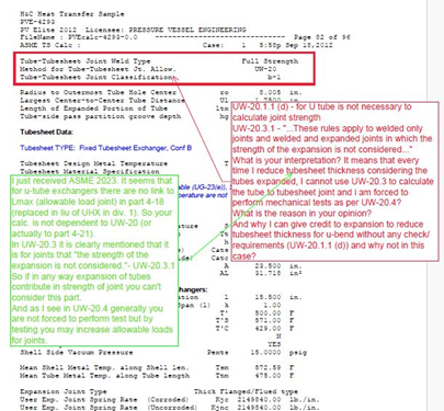
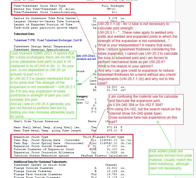
1) Issue: UW-20.1.1 (d) – for U tube is not necessary to calculate joint strength
UW-20.3.1 – “…These rules apply to welded only joints and welded and expanded joints in which the strength of the expansion is not considered…”
What is your interpretation? It means that every time I reduce tubesheet thickness considering the tubes expanded, I cannot use UW-20.3 to calculate the tube to tubesheet joint and i am forced to perform mechanical tests as per UW-20.4?
What is the reason in your opinion?
And why I can give credit to expansion to reduce tubesheet thickness for u-bend without any check/requirements (UW-20.1.1 (d)) and why not in this case?
Solution: I just received ASME 2023. It seems that for u-tube exchangers there are no link to Lmax (allowable load joint) in part 4-18 (replaced in liu of UHX in div. 1). So your calc. is not dependent to UW-20 (or actually to part 4-21).
In UW-20.3 it is clearly mentioned that it is for joints that “the strength of the expansion is not considered.”- UW-20.3.1
So if in any way expansion of tubes contribute in strength of joint you can’t consider this part.
And as I see in UW-20.4 generally you are not forced to perform test but by testing you may increase allowable loads for joints.
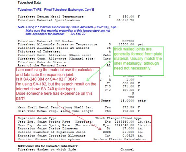
2) Issue: I am confusing the material use for calculate and fabricate the expansion joint.
Is it SA-240 304 or SA-182 F 304?
I’m using SA-182, but the search result on the internet show SA-240 (plate type).
Dose someone here has experience on this part?
Solution: thick walled joints are generally formed from plate material. Usually match the shell metallurgy, although need not necessarily.
3) Issue: If the calculated weld size is insufficient to withstand applied loads, it can lead to weld failure or joint separation.
Solution: Review the applied loads and re-calculate the required weld size based on updated design parameters and welding standards.
4) Issue: Mismatched materials between the tubesheet and adjoining components can result in weld joint issues, such as galvanic corrosion or metallurgical incompatibility.
Solution: Ensure that materials are compatible and meet code requirements for joint welding.
5) Issue: Incorrect assessment of loading conditions, such as pressure, thermal expansion, or dynamic loads, can lead to under-designed or over-designed weld joints.
Solution: Verify loading conditions and perform a thorough analysis to determine the appropriate weld joint design.
6) Issue: Non-compliance with applicable welding codes and standards can result in weld joint failures or regulatory issues.
Solution: Ensure that weld joint calculations adhere to relevant codes and standards, such as ASME Boiler and Pressure Vessel Code, Section VIII, Division 1.
Conclusion
In conclusion, addressing issues with tube sheet weld joint calculations is crucial for ensuring the integrity, reliability, and safety of shell and tube heat exchangers. By identifying common issues such as inadequate weld size, material compatibility issues, loading condition inaccuracies, code compliance issues, weld quality concerns, residual stresses, and fatigue considerations, engineers can implement appropriate solutions. These solutions may include recalculating weld sizes, verifying material compatibility, ensuring accurate loading assessments, adhering to welding codes and standards, improving weld quality control measures, mitigating residual stresses, considering fatigue analysis, and maintaining thorough documentation and review processes. By proactively addressing these issues and implementing effective solutions, engineers can enhance the performance and longevity of tube sheet weld joints, ultimately contributing to the overall reliability and safety of shell and tube heat exchangers in industrial applications.
Get detailed/ Get files/ Get customized/ Get trained by click link given here https://shreeaasaantech.com/contact-us/
