EXAMPLE OF FLANGE CALCULATIONS
Flange
A flange is a projecting flat rim, collar, or rib on an object, typically designed for attachment, reinforcement, or connection to another object. In engineering and construction, flanges are commonly used in piping systems, structural connections, and equipment assembly. Here are some common types and applications of flanges
Equipment Flanges: Flanges are often used to attach equipment, such as pumps, compressors, heat exchangers, and vessels, to structural supports or piping systems. Equipment flanges provide a secure and leak-proof connection between the equipment and associated components.
Flanges play a crucial role in pressure vessels:
1) Connection Points: Flanges serve as connection points between various components of a pressure vessel, such as pipes, valves, fittings, and other vessels. They allow for easy assembly and disassembly during construction, maintenance, and repair activities.
2) Sealing: Flanges provide a means of creating a sealed joint between different parts of the pressure vessel. By using gaskets or other sealing materials between flange faces, leakage of fluids or gases from the vessel can be prevented, ensuring safety and integrity.
3) Pressure Containment: Flanges are designed to withstand the internal pressure of the vessel and ensure containment of the pressurized fluids or gases. Proper selection of flange materials, design, and dimensions is essential to prevent failure or leakage under pressure.
4) Flexibility: Flanged connections offer flexibility in the design and layout of pressure vessels, allowing for easy adaptation to changing operational requirements, process conditions, or future modifications. Flanges enable the addition or removal of components without significant disruption to the vessel’s structure.
5) Support and Reinforcement: Flanges provide support and reinforcement to critical areas of the pressure vessel, such as openings, connections, and transitions between different sections. They help distribute loads, minimize stress concentrations, and enhance the overall structural integrity of the vessel.
6) Compatibility: Flanges allow for compatibility between different pressure vessel components, as they can accommodate various sizes, types, and materials of pipes, fittings, and equipment. This compatibility facilitates integration with other systems and ensures seamless operation of the vessel within the overall process or facility.
7) Regulatory Compliance: Flanges must meet regulatory requirements and industry standards governing the design, fabrication, and operation of pressure vessels. Compliance with standards such as ASME Boiler and Pressure Vessel Code ensures that flanged connections are safe, reliable, and suitable for their intended applications.
Importance of flange calculation
Flange calculations for pressure vessels are crucial for ensuring the integrity, safety, and performance of the vessel under various operating conditions. Here are some key aspects highlighting the importance of flange calculations:
1) Pressure Containment: Flanges are critical components in pressure vessels as they form joints between different sections of the vessel, such as heads, shells, nozzles, and fittings. Flange calculations help determine the appropriate dimensions, materials, and configurations needed to withstand the internal pressure of the vessel and ensure containment of the pressurized fluid or gas.
2) Leakage Prevention: Flange calculations ensure the proper design of flanged connections to prevent leakage of hazardous or valuable fluids from the pressure vessel. By considering factors such as bolt preload, gasket compression, flange facing, and surface finish, engineers can establish effective sealing mechanisms that minimize the risk of leaks and ensure operational safety.
3) Bolted Joint Integrity: Flange calculations involve analyzing the behavior of bolted joints under operating conditions, including bolt tensile stresses, bolt preload, bolt relaxation, and joint deflection. Proper bolt sizing, spacing, and tightening procedures are essential to achieve and maintain the desired clamping force and prevent joint separation or failure.
4) Flange Loading and Stress Analysis: Flange calculations assess the mechanical loading and stress distribution in flanged connections due to internal pressure, external loads, thermal expansion, and other factors. Engineers evaluate the flange geometry, material properties, and boundary conditions to determine the stresses acting on the flange, bolted joint, and adjacent components, ensuring structural integrity and fatigue resistance.
5) Code Compliance: Flange calculations must comply with relevant industry standards and codes, such as ASME Boiler and Pressure Vessel Code (BPVC) Section VIII for pressure vessel design. Adherence to code requirements ensures that flanged connections are designed, fabricated, and inspected according to established best practices and safety guidelines.
6) Operational Reliability: Flange calculations contribute to the reliability and performance of pressure vessels by identifying potential issues, such as flange overloading, gasket blowout, bolt yield, or joint relaxation, that could compromise the vessel’s integrity or functionality. By addressing these concerns during the design phase, engineers can enhance the reliability and longevity of the vessel in service.
7) Cost Optimization: Flange calculations help optimize the design of pressure vessel flanges by balancing performance requirements with cost considerations. Engineers strive to achieve efficient designs that meet safety, quality, and regulatory requirements while minimizing material usage, fabrication complexity, and maintenance expenses.
Issues and Solutions on Flange Calculation
Flange calculations are critical in ensuring the integrity and reliability of flanged connections in various engineering applications.
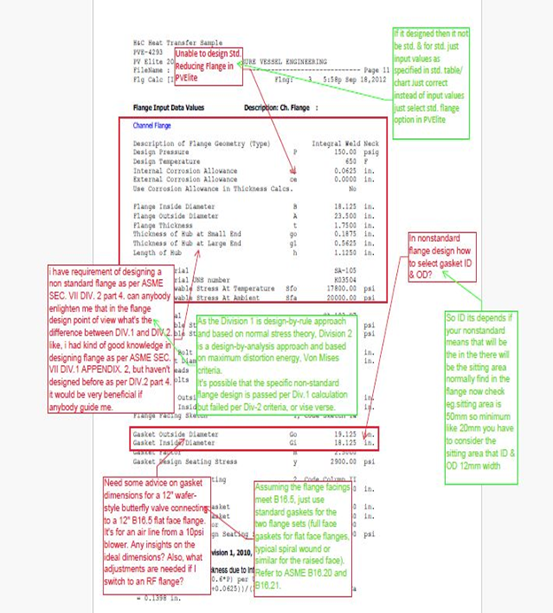
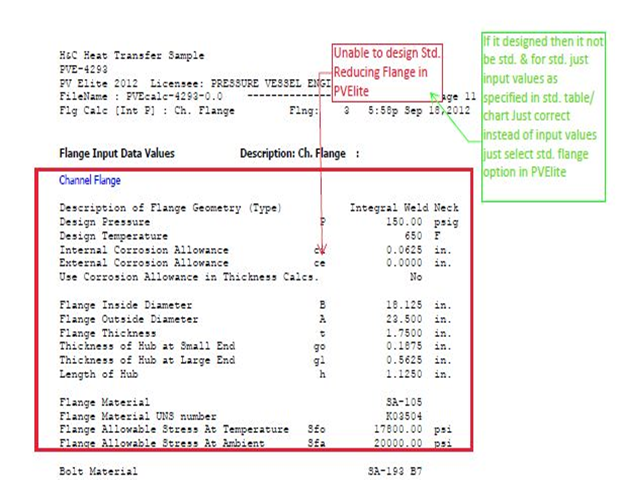
1) Issue: Unable to design Std. Reducing Flange in PVElite
Solution: If it designed then it not be std. & for std. just input values as specified in std. table/chart Just correct instead of input values just select std. flange option in PVElite
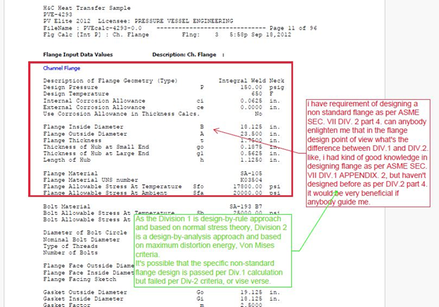
2) Issue: I have requirement of designing a non-standard flange as per ASME SEC. VII DIV. 2 part 4. can anybody enlighten me that in the flange design point of view what’s the difference between DIV.1 and DIV.2. like, i had kind of good knowledge in designing flange as per ASME SEC. VII DIV.1 APPENDIX. 2, but haven’t designed before as per DIV.2 part 4.
it would be very beneficial if anybody guide me.
Solution: As the Division 1 is design-by-rule approach and based on normal stress theory, Division 2 is a design-by-analysis approach and based on maximum distortion energy, Von Mises criteria.
It’s possible that the specific non-standard flange design is passed per Div.1 calculation but failed per Div-2 criteria, or vise verse.
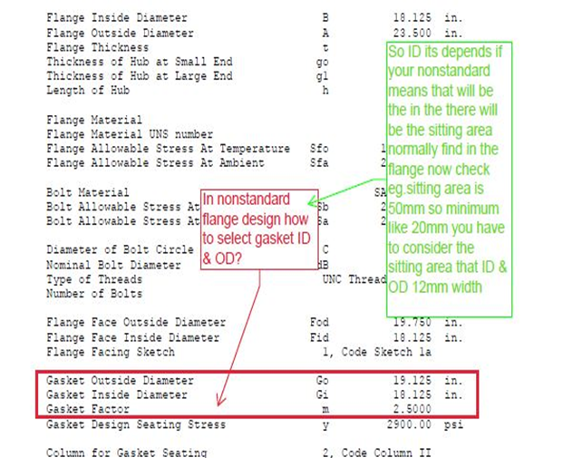
3) Issue: In nonstandard flange design how to select gasket ID & OD?
Solution: So ID its depends if your nonstandard means that will be the in the there will be the sitting area normally find in the flange now check e.g. sitting area is 50mm so minimum like 20mm you have to consider the sitting area that ID & OD 12mm width
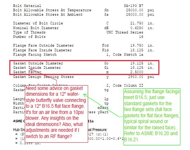
4) Issue: Need some advice on gasket dimensions for a 12″ wafer-style butterfly valve connecting to a 12″ B16.5 flat face flange. It’s for an air line from a 10psi blower. Any insights on the ideal dimensions? Also, what adjustments are needed if I switch to an RF flange?
Solution: Assuming the flange facings meet B16.5, just use standard gaskets for the two flange sets (full face gaskets for flat face flanges, typical spiral wound or similar for the raised face). Refer to ASME B16.20 and B16.21.
5) Issue: One of the primary causes of flange joint failure is inadequate or excessive bolt preload, leading to leakage or joint separation. This issue can occur due to inaccurate bolt tightening procedures, improper bolt selection, or insufficient understanding of bolt behavior under load.
Solution: Ensure that bolt preload is calculated accurately based on the required gasket stress and joint conditions. Use proper bolt tightening techniques, such as torque or tensioning methods, and consider factors such as bolt material, size, and lubrication to achieve the desired preload.
6) Issue: Selecting the wrong gasket material or thickness, or applying incorrect gasket compression, can result in flange leakage or failure. Gasket issues may arise due to insufficient resilience, chemical compatibility issues, or improper installation practices.
Solution: Choose gasket materials and designs that are suitable for the specific application, considering factors such as temperature, pressure, fluid compatibility, and flange surface finish. Follow manufacturer recommendations for gasket installation, including proper compression levels and torque values.
7) Issue: Inadequate flange facing or surface roughness can compromise the sealing performance of the flanged joint, leading to leakage or gasket damage. Issues may arise due to improper machining practices, corrosion, or damage during handling.
Solution: Ensure that flange faces are machined to the specified flatness and surface finish requirements outlined in industry standards or manufacturer recommendations. Address any surface irregularities, corrosion, or damage through proper repair or refinishing techniques.
8) Issue: Flange calculations should account for the complex behavior of bolted joints under load, including bolt elongation, relaxation, and stress distribution. Neglecting these factors can result in under-designed or over-designed flanged connections.
Solution: Perform detailed bolted joint analysis using appropriate analytical methods, such as finite element analysis (FEA) or hand calculations, to assess bolt behavior under operating conditions.
Conclusion
In conclusion, flange calculations are essential for ensuring the integrity, reliability, and safety of flanged connections in various engineering applications. Despite their importance, flange calculations can present challenges and issues that need to be addressed effectively. By understanding common issues and implementing appropriate solutions, engineers can optimize flange design, prevent joint failure, and enhance the overall performance of pressure vessels, piping systems, and other structures. Collaboration between mechanical engineers, materials specialists, and design professionals is crucial for conducting thorough flange calculations and achieving successful outcomes. Ultimately, a systematic approach to flange design, including accurate bolt preload determination, proper gasket selection, meticulous surface preparation, detailed joint analysis, and adherence to industry standards, is essential for ensuring the reliability and longevity of flanged connections in engineering applications.
By addressing these common issues and implementing appropriate solutions, engineers can ensure the reliability, integrity, and safety of flanged connections in various engineering systems and applications. Collaboration with experienced professionals and adherence to best practices and industry standards are essential for successful flange calculations and design.
Get detailed/ Get files/ Get customized/ Get trained by click link given here https://shreeaasaantech.com/contact-us/
